String Bass Effect and MIDI on a C2
North Suburban HAMMOND ORGAN Service
Here is a simplified schematic of an individual string or sustain bass keyer. This is typical, although individual resistor and capacitor values are different depending on the frequency, but it is indeed possible to have all similar components for each pitch the same. Slight improvements result by making the input signal capacitors bigger for lower frequencies and by using smaller sustain capacitors on higher frequencies.
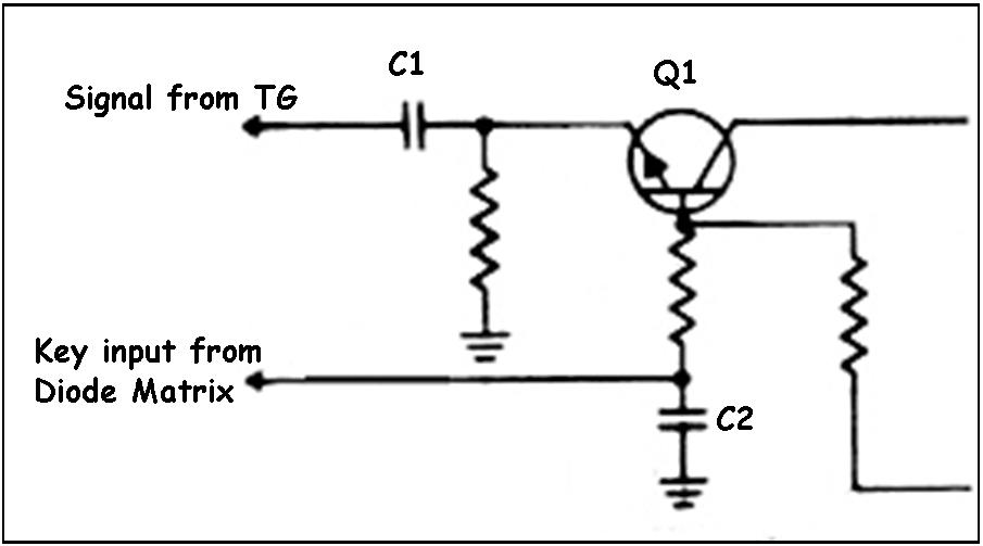
Because a string bass pedal tone must not cut off abruptly when you release a pedal but instead fade out, this means that a pedal tone must be available even when a pedal is not held down. Therefore, all pitches which we use for pedal string bass get applied to the inputs of each keyer permanently. The signals come in via the input coupling capacitors and connect directly to the emitters of the keying transistors noted as "Q1" in the schematic below. There are many low-level signal transistors that are possible to use; the circuit is not overly critical. I used 2N3393s as I still have many left over from previous projects, although a 2N3393 is not a new transistor at all. These might be 40 to 50 years old, but they keep indefinitely and it is not really until you put them in service that you need to worry about them becoming used. And in service like this, they will last for decades.

Figure 7.This is a typical sustain keyer for one pedal bass note. The signal comes in from the Hammond tone generator as noted, goes through the DC blocking capacitor listed as C1 which keeps any DC voltage present on the emitter of the transistor out of the original Hammond TG and keyboard circuitry. This signal is always present when the instrument is turned on. Below that is a keying input from the diode matrix relay.
When you step on a pedal, the relay applies 4 volts of DC to the base of the keying transistor which makes the transistor conduct and amplify the signal appearing on its emitter. The gain of the circuit depends on the DC voltage applied to the base of the transistor. As long as you hold a pedal down, the transistor will pass the signal, which leaves from its collector and goes out on the wire shown as the upper right hand line. At the same time, this also charges capacitor C2 to 4 volts.
When you let go of the pedal, C2 gradually discharges through the resistor attached to the base of the transistor, and the voltage therefore gradually drops to zero. As this happens, the transistor continues to pass the signal, but the gain gradually decreases as the voltage drops and therefore the signal fades out. The rate of fade depends primarily on the value of C2, the value of the base resistor attached to the transistor, the base resistance of the transistor, and also upon a variable bias voltage which is introduced through a resistor from the wire at the lower right of the picture. Therefore, by varying the bias voltage, we may control how long it will take the transistor to continue passing at least some signal. We select parts for this circuit so that the musician may vary this time from a maximum of 2 seconds to a minimum of 0.25 sec which is a typical useful range for string bass. You can entirely eliminate the string bass effect if you desire by turning its volume control to zero.
As you can see, by using transistors, we can make an individual sustain circuit that is relatively small and simple. Furthermore, the amount of heat produced and dissipated is negligible, which is why circuitry such as this would be impractical using vacuum tubes, but very simple and easy with transistors. The whole secret of a sustain circuit is that it must allow the signal to persist and gradually fade AFTER you have let go of a key or pedal. This is made possible by changing the function of a key or pedal contact from switching the actual audio signal, to switching a controlling or operating DC voltage to a keying circuit which controls the actual audio signal.

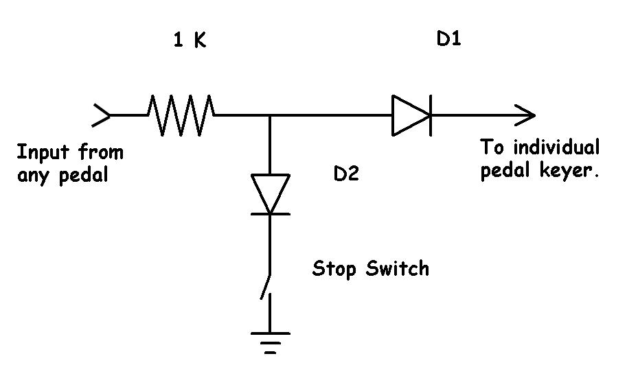
Figure 8. Typical diode matrix relay for one pedal that selects appropriate keyers for 32', 16' or 8' string bass pitch. A +4 VDC from a pedal goes through a 1 K current limiting resistor which does two things. First, when a stop is off, it prevents a direct short circuit to ground of the keying voltage when you step on a pedal. Second, in conjunction with the sustain capacitor in the actual keyer, it slightly slows the capacitor charging time which eliminates a loud pop at the start of each pedal tone.
If a pedal stop is ON, the four volt DC continues on to the appropriate keyer through D1. If a pedal stop is off, then D2 gets connected to ground. In this case, the 4 volt keying input from a pedal gets shorted to ground and does not activate the associated pedal keyer. Since in this system it is possible for most of the pedal keyers to be played from at least two and possibly even three different pedals, diode D1 in the output path prevents phantom signal paths from developing which could otherwise result in many unwanted additional keyers from operating. Diode D2 does the same thing in the grounding paths, that is, preventing phantom paths between keyers from developing. Note that the negative ends of all of the D2 diodes for any particular pitch of the string bass are connected together, and that when a stop is off, there is just one stop switch to ground for all twenty-five diodes for that stop. When a stop is on all of the negatives "float" and since they are connected together, we have to use diodes here to prevent any backwards current flow from one keyer to another, so that unwanted pedal tones will not sound.
In reality, what the string bass circuit does is to allow any of the first 37 Hammond tone generator frequencies to be independently played from the pedals, and to control the attack and decay of the audio signal of each pedal via a small transistor amplifier whose gain is variable and controlled by a small DC voltage on the base of the transistor. By using a capacitor in the base circuit, we can make the base voltage gradually fade to zero AFTER we have released a pedal, which then allows the tone to continue to sound, but also to fade as the base voltage on the capacitor gradually lowers. An adjustable bias voltage applied at the base of each keyer transistor through an additional resistor varies the rate at which the base capacitor discharges which in turn varies the decay time, or length of sustain after we release a pedal. The collectors of these transistors are constantly supplied with 20 volts DC, and are commoned together in two groups, 1-12, and 13-37. The reason for this is that in suffix-2 and suffix -3 traditional Hammond organs, tonewheels 1-12 are shaped by Hammond to generate a complex tone and not a sinewave, and also the tonewheel output for 1-12 is greater than that of the others. So we must use a little extra attenuation and lo-pass filtering to make them have the same level as tonewheels 13-37, and also to filter out the extra harmonic content. Thus, there are two inputs on the string bass preamp, one for 1-12, and the other for 13-37. The output of the preamp appears across a 10K pot so that we can control the volume of the string bass relative to the rest of the Hammond, after which it passes through a 220K ohm resistor into the no-vibrato input on the Hammond preamp. Because vibrato on bass tones generally does not sound good, I did not make any provision for switching the string bass output signals into the vibrato-on channel on the Hammond preamp.
Home Page Page4. Next page | Previous page