The PIPE ORGAN
North Suburban HAMMOND ORGAN Service
Specific sub-systems - The Winding System
Another regulator valve arrangement which you will find is the triple valve regulator system used by Wurlitzer and several other builders of theater organs. In this regulator, there is a very small cone valve, usually only a couple of inches in diameter. There are also two additional pallet valves of different sizes. You can think of a pallet valves as being like a door that is hinged at one edge. The arrangement is such that these valves open sequentially. If the air demand is very small, the top of the regulator will only descend a very short distance and will open only the cone valve. If the wind demand increases, then the smaller of the two pallet valves will open a little also, and of course the cone valve will have opened a little more. If the demand is still bigger, a slight addition drop of the regulator top opens the large pallet valve.
The theory behind this arrangement is that because the small cone valve has a small surface area, when the demend is low and the blower pressure is higher; and therefore the differential pressure across the valves is greater, the FAP rule says that the force on the small pallet valve will not be significant enough to have any performance-altering influence on the regulator control function. When demand is greater, blower pressure of course drops, thus when the large pallet valve is open, the pressure differential across the valve will be less.
Wurlitzer, Robert-Morton, and Kilgen all used these multiple valve regulators with good results. But many other builders have found that just a single cone valve with an exponential profile will work just as well in practice. But in well designed triple valve regulators, the tops will usually not descend more than one inch, which still keeps the springs on the best part of the spring performance curve and keeps the output pressure steady and accurate.
The spring performance curve graph is as follows.
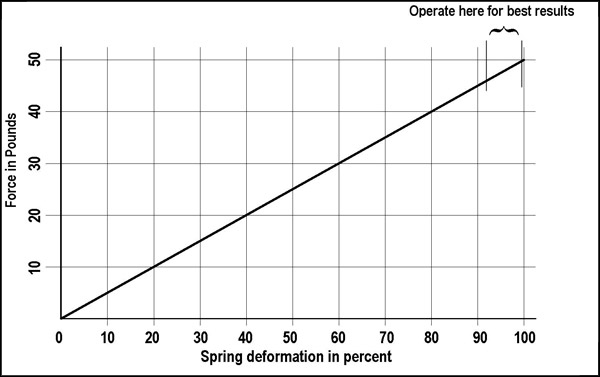
This diagram shows how a spring behaves when stretched but not beyond its elastic limit. For a pipe organ pressure regulator, we need to be operating in the small region as shown. The idea is that the change in force due to the stretching changes created by minute air pressure differences in the pressure regulator should be only a very minute portion of the total stretch force on the spring. By keeping both the strecth force and the length change of the sprng as small as possible, then essentially the force developed by the spring will be almost absolutely constant, which therefor makes the pressure of the air delivered by the regulator constant also.
Notice on the above graph the area where it says "operate here." This graph shows the linear portion of the spring curve for a 50 pound spring. If you stretch the spring too far beyond the limit, it will permanently deform and not return to its original shape when the force is removed. The important thing to notice is that compared to the amount of deformation of the spring, the "operate here" region is very small, and the difference in tension is a very small percentage of the total. If, on the other hand, you operate closer to the zero point, the change in the spring is a much larger percentage of the total deformation. Therefore, it is necessary to preload, or stretch the spring initially so that it is already stretched before the wind enters the regulator and raises the top. This also shows why a very small motion of the top of the regulator is necessary, and why a large motion of the top will result in noticeable pressure sags. It's also worth noting that in this graph, the "operate here" region as about as big is it ever should be, and if it is smaller, the regulator will give better pressure control.
Although it is not printed on the above graph, the length of a typical coil spring would be about 15" when the regulator top is at the top end of its travel, and the "operate here" region is about one inch, which would be typical for a three-valve Wurlitzer regulator. Obviously, if we can reduce the motion of the regulator top to a half inch or even less, the regulation gets even better. Although relatively speaking, the air pressure in the regulator is low, we are dealing with large surface areas. Many regulators are around 2 feet × 3 feet in size, and some are a lot bigger than that. If you have a wind pressure of 10" of water, you have a pressure of 0.36 PSI. If the area of the regulator is 2 × 3 feet or 6 square feet, it represents 864 square inches. With an air pressure of 0.36 PSI acting on an area of 864 square inches, the force developed is 311 pounds. Therefore, you will need a spring force of 311 pounds to make this regulator produce an output pressure of 10" of water. You therefore need a minimum of six 50 lb springs, and even that would not be quite enough, for you technically would need 6.22 springs, or an additional eleven pounds, but obviously you can't have a fraction of a spring! But you could add a couple of five pound springs and be close enough. Plus the top of the regulator will have some weight of its own which would probably be more than enough. And if the wind pressure ended up being 9.98 inches, or 10.02 inches, that small difference would not present a problem in actuality even though it is not exactly what the specs called for.
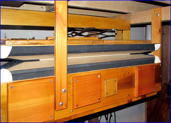
Typical pressure regulator, 24" X 36" controlling the pressure to one division of a large pipe organ. This regulator reduces the pressure from the distribution line from 6" H2O to 4" H2O for the pipes in this division. The numberous covers that you see on the side are for extra air outlets. It is much easier to make extra outlet holes during the fabrication of the regulator and then cover over those that are not needed in actual service than to cut holes in a regulator at the job site.
No pressure regulator is absolutely perfect. Slight non-linearities are always encountered. Besides a change in spring tension with the amount of deformation, another factor is the toggle action of the folding sides of the bellows portion of the pressure regulator. As the sides unfold (as top rises) the sideways force of the air pressure within pushes the sides out and like any typical toggle action, this adds more upward force. Therefore, when the top of the regulator is high up enough that the folding sides are more in line, then this helps to push the top higher and introduces another force that has to be considered. To obviate this difficulty the folding sides should always be at small angle to each other which then implies that the folding sides should definitely have less than a 90° included angle, and of course the less this angle changes with a change in regulator top position, the better, which is yet another reason why the movement of the top should be less than an inch.
In some pipe organs where there are a number of different pressures used and the blower pressure, which is always higher than the highest pressure in the organ, is considerably higher than the lowest pressure in that same instrument, a pipe organ builder may use a regulator right after the blower to lower the distribution pressure so that when the demand is very low and the blower pressure is relatively high, then the distribution pressure itself will be just above the highest pressure in the instrument, or he may install a pressure regulator in the distribution line which feeds the lower pressure section ahead of the regulator that actually controls the pressure to the pipes in the low pressure section. Pipe organ pressure regulators work better if the pressure differential across them is not too great; that is, the regulated pressure that they supply to the pipes should be just a little lower than their input supply pressure.
It is possible to achieve very good pressure control in the modern pipe organ so that pressure sags and hiccups in pipe speech are just about entirely eliminated. Now, I mentioned before that there is one instance in pipe organs where the pressure to the pipes is deliberately varied, and that is when a tremulant is part of the system.
Previous Page Page 11.
Next page